Four servos, a gripper, and a point in front of the arm. To land the gripper on that point, what angle does each servo take?
That’s inverse kinematics, and it’s the hard direction. Forward, angles to position, is a line of trig; the inverse runs backwards, and a point can have more than one set of angles or none at all. This is how I solved it for a cheap desk arm, and how the real servos made me redo it.
the setup
The arm is a Keyestudio KS0198,
a cheap 4-DoF kit: a base that rotates, two servos that drive the arm links, and
a servo for the gripper. The two arm servos don’t sit at the joints in series;
both sit at the shoulder and drive a parallelogram linkage: a set of rigid
bars pinned together, four of them here, arranged in a rhombus. That parallelogram
keeps the gripper’s orientation fixed no matter how the arm is posed, and holds
the whole mechanism in a single vertical plane. Two angles come out of it: θ₁,
the green link, and θ₂, the blue one.
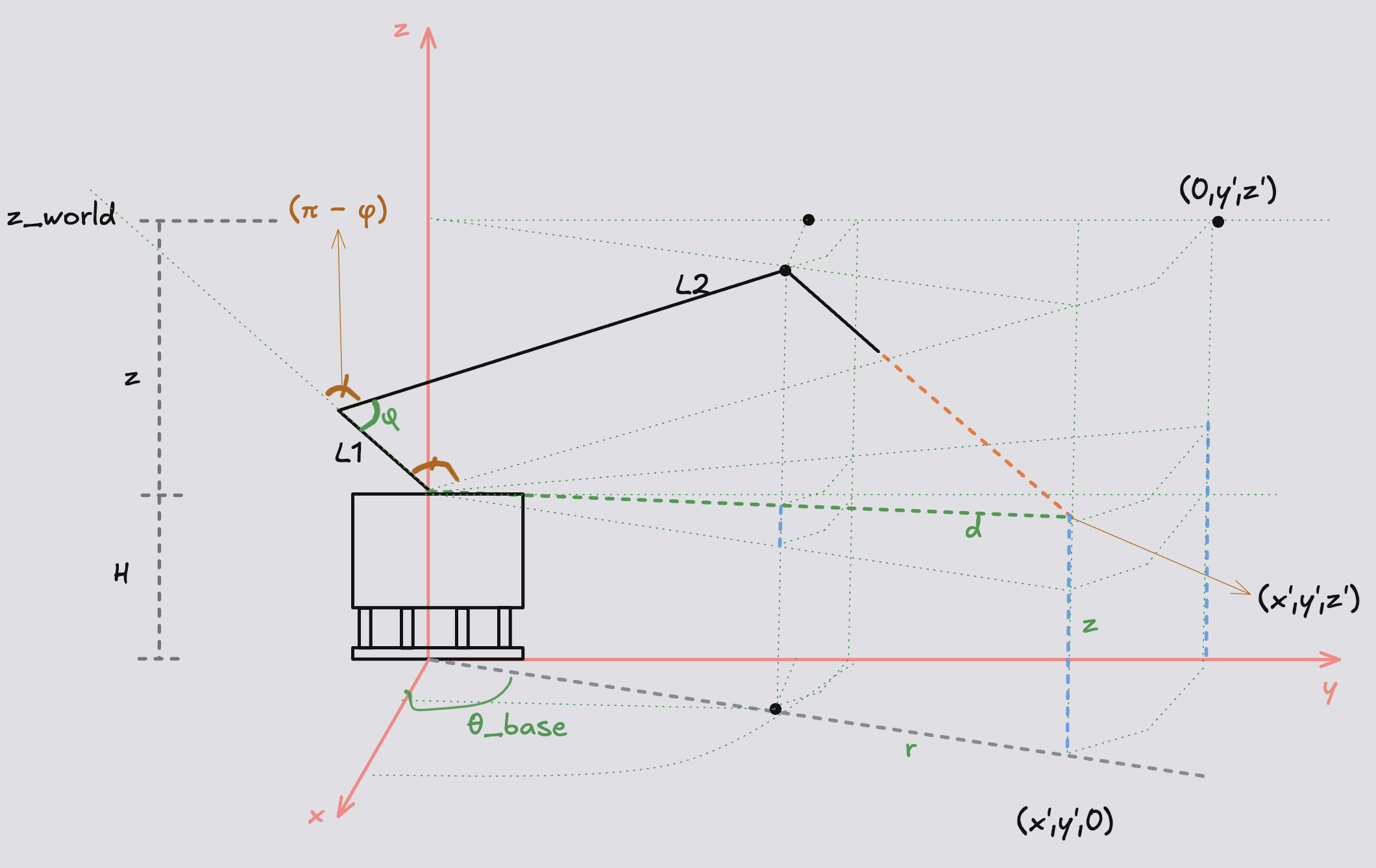
The 3D view. The base angle θ_base peels off the horizontal direction, and what’s left is a flat (r, z) problem in the plane the arm swings through; d is the shoulder-to-target distance the next section is built on.
That linkage splits the 3D problem into two easy pieces.
The base handles the horizontal direction. Seen from directly above, the
target sits at (x, y) and the base just turns to face it: θ_base = atan2(y, x),
with r the horizontal distance out to it.
Everything else happens in the vertical plane the base is now facing. In that
plane the target is (r, z), with r how far out and z how high, and the arm
is a two-link problem I have a hope of solving by hand.
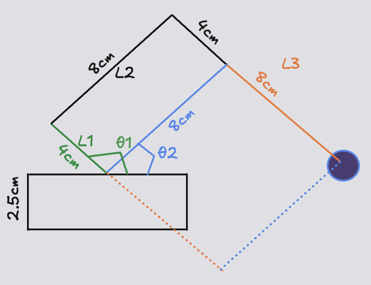
The linkage in its vertical plane. The two servos set θ₁ (green) and θ₂ (blue) at the shoulder, and the bars carry that into the gripper’s position (the dark circle).
The bars are short (the blue and orange links are 8 cm, the green one 4 cm), but
the geometry is arranged so that, from the shoulder, the gripper ends up at the
tip of two effective 8 cm links: the blue bar and the orange one. The short
green bar and its parallel partner are the parallelogram struts, there to keep the
orange link pointing the way θ₁ says.
So the real work is 2D: two links of 8 cm, a target at (r, z), find the angles.
the derivation
The whole solve is four lines:
d  = √(r² + z²)
D  = acos(1 − d²/128) / 2
S  = atan2(−r, z)
θ₁ = S + D + 180°
θ₂ = S − D + 180°
Everything else is just that triangle, unpacked.
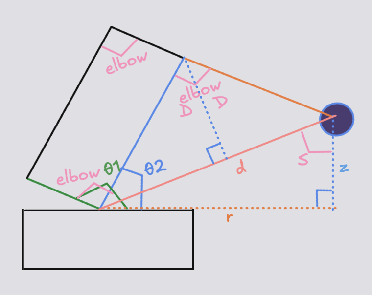
The derivation triangle. The two 8 cm links and the reach d form an isosceles triangle; the elbow angle is 2D, and S is the angle between d and the vertical.
The shoulder, the elbow, and the target form a triangle: the two 8 cm links as
its sides, the reach d as its base. Every line above comes off it.
d is the distance to the target, √(r² + z²). Two 8 cm links can’t reach
past 16 cm, so if d > 16 the point is unreachable and the code bails before it
hits a NaN.
D is half the elbow bend. The triangle is isosceles, so the law of cosines
gives the elbow angle straight away:
d² = 8² + 8² − 2·8·8·cos(elbow) → cos(elbow) = 1 − d²/128S is the aim: the angle between d and the vertical, atan2(−r, z). It’s
atan2 rather than plain atan so it keeps the sign of r (target in front vs
behind) and doesn’t blow up when z = 0; the −r only sets which side counts as
positive.
The servo angles then read straight off the figure, as angles up from the
table. The blue link (θ₂) is the climb up to d plus the base angle across to
it; the green link (θ₁) is one whole elbow (2D) further around:
θ₂ = (90 − S) + (90 − D) = 180 − S − D
θ₁ = θ₂ + 2D             = 180 − S + D
atan2(−r, z) returns S with the opposite sign, so flipping S → −S lands
them in the form the code runs:
θ₁ = S + D + 180
θ₂ = S − D + 180
In code it’s as short as the math (simulator.py):
def ik_rhombus(r, z):                       # r, z measured from the shoulder
    d = np.hypot(r, z)
    if d > REACH or d < 1e-6:
        return None                      # unreachable: refuse to guess
    arg   = np.clip(1.0 - (d*d)/(2*L*L), -1.0, 1.0)
    elbow = np.arccos(arg)                 # full elbow angle (= 2D)
    D     = elbow / 2                      # half the elbow
    S     = np.arctan2(-r, z)              # aim at the target
    th1   = np.degrees(S + D + np.pi)      # θ1 = S + D + 180
    th2   = np.degrees(S - D + np.pi)      # θ2 = S − D + 180
    return th1, th2
One note the plot makes obvious but the equations hide: z here is measured from
the shoulder, and the shoulder sits 2.5 cm above the table. So a target you
describe as “4 cm off the table” enters the solve as z = 1.5. A small
bookkeeping thing that will absolutely bite you if you forget it.
when the robot disagrees with the math
The clean way to do this is to simulate first. I did it backwards: I took the equations straight to the real arm, commanded a clean, reachable pose, and it went somewhere else. Not randomly wrong. Mirror wrong. The elbow that should have lifted dropped; the pose was a reflection of the one I’d asked for.
The map from “angle in my model” to “number I write to a servo” was not the identity function, and I’d assumed it was. Two separate things were off.
The mounting was mirrored. One of the two arm servos is bolted on facing the opposite way, so its rotation runs backwards relative to the plane my math lives in. The fix is one line, but you only find it by watching the real arm move the wrong way:
// right moves L1 (theta1).
// REFERENCE CONVERSION: the servo's real 0 = 180 in the model.
double real_deg = 180.0 - degrees;
real = 180 − model. Without it, the arm reaches for the mirror image of the
point instead of the point itself.
The servos need calibrating. Each one has its own offset and slope, and (this
surprised me) the numbers move with the power supply: calibrated over USB, the
arm drifted once I put it on batteries. So I re-measured every servo under the
power it actually runs on, commanding known values and reading back the real angle
with the level app on my phone, then fit a line through the points
(kinematics.cpp):
int angleToServoRight(double degrees) {
    double real_deg = 180.0 - degrees;   // the mirror, from above
    // measured under battery power (cmd60->38, 80->60, 100->79, 120->99):
    //   real_angle = 1.01*cmd - 21.9  ->  cmd = (real_angle + 21.9)/1.01
    int cmd = std::lround((real_deg + 21.9) / 1.01);
    return clamp(cmd, 0, 125);
}
The left servo got the same treatment with its own, different constants. The clean
θ₁ = S + D + 180° from the derivation is only the first of three steps; the
real command is mirror → affine calibration → clamp, and every constant in
those last two steps was measured off the physical arm, not derived.
None of this was a bug in the math. The model was right; it just didn’t know how a servo was bolted on, what voltage it ran at, or where its real zero sat. That kind of thing doesn’t show up in the equations. You get it by moving the real arm and seeing where it goes.
so I built a simulator
After enough of that, I stopped and built the thing I should have built first: a simulator.
The motivation was mostly the servos. They’re cheap, and a cheap servo asked to hold an impossible pose doesn’t error out. It strains, buzzes, draws current, and strips its own plastic gears. A bad angle isn’t a stack trace, it’s a dead servo, and I’d already fed the arm a few.
The simulator (simulator.py)
draws the arm and, for every target, shows the model angles the equations
produce, the reach circle (that d ≤ 16 limit, drawn as a boundary you can
watch the gripper bump against), and the servo commands they turn into, mirror
and calibration baked in. Drag the target out of reach and it turns red and
says UNREACHABLE instead of quietly feeding the arm garbage.
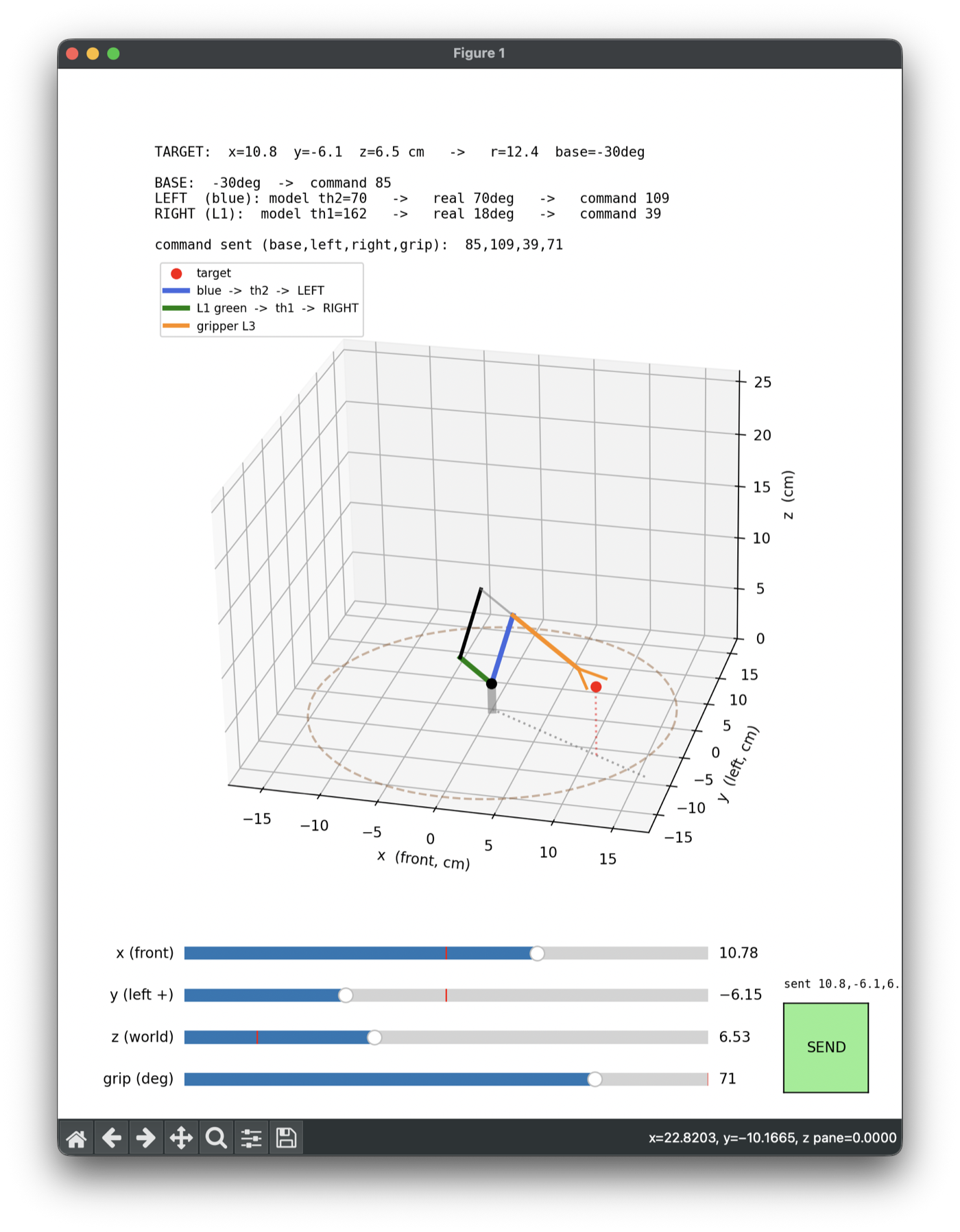
The simulator: sliders for x, y, z and the gripper, and a SEND button. The command sent line is a preview of what kinematics will produce; what actually goes out is the target itself, x, y, z and the grip angle.
This is the cheap, fast loop I should have started with: I could sweep the entire workspace, watch the arm fold and unfold, and catch every impossible pose in pixels before it cost me another gearbox.
wiring it to the robot
In the simulator all of this runs on my laptop. The arm itself is driven by a Raspberry Pi sitting next to it, with the control code running there as a ROS2 node, in a Docker container, rewritten in C++: the same four equations, one level closer to the metal.
It’s three small nodes passing messages
(arm_control):
/target_position ─┐
                  ├─► kinematics ─► /joint_commands ─► arm_driver ─► serial ─► Arduino
/grip_command ────┘
Everything left of kinematics speaks world coordinates: a client hands the
system a point in centimetres and never mentions an angle. Everything right of
it speaks servo angles: they’re born inside kinematics and travel as the four
numbers base,left,right,grip down to an Arduino that is deliberately dumb; it
knows nothing about geometry and just eases the servos to whatever four numbers
arrive. The gripper is the one exception to the split (a target point can’t
tell you how open the claw should be), so it rides its own topic straight
through the math.
That split is the whole point: when a later post bolts a camera on, that’s just one more node publishing targets in centimetres, with no idea the word “servo” exists.
the payoff
With the mirror and the calibration in place, the two finally agree. I hand the arm a coordinate, the same four equations run, the three-step conversion turns them into servo commands, and the gripper lands on the point.
what’s next
Right now the arm is open-loop and blind. It trusts that a command becomes a pose, because nothing tells it otherwise. These servos don’t report their real position back, so the arm’s idea of “where I am” is really just “what I last asked for.” That’s fine when the world is exactly where the math expects it, and it’s the first thing that breaks the moment it isn’t.
So the next step is to give it eyes: a camera, and a policy that maps what it sees to where it moves, pick-and-place on an object it has to actually find rather than be handed the coordinates of. That’s a different kind of problem, and a bigger post.
Point in, angles out, once the equations knew what the real servos were doing.